| Revision History | |
|---|---|
| Revision 1 | 11.12.2006 |
|
Initial version | |
Table of Contents
- 1. Creating simple advanced objects
- 2. Creating and using texture OVLs
- 3. Creating working lights
- 4. Creating particle effect points
- 5. Creating firework launchers
- 6. Creating working benches
- 7. Creating billboards and scrolling signs
- 8. Creating stalls and special attractions
- 9. Working with Levels of Detail (LODs)
- 10. Working with transparent textures
- 11. Creating and using recolorable textures
- 12. Creating and using animated textures
- 13. Extensive discussion of texture styles
- 14. Credits
This tutorial will show you various advanced techniques using the RCT3 Custom Scenery Importer.
This document applies to the RCT3 Importer Version 16fix5.
Set Extra Parameters and Scenery Type to Litter Bin in the scenery settings. Set the Size Flag to Path Edge (Inner). Maybe Path Edge (Outer) works as well.
Set Extra Parameters to Passport Post in the scenery settings. Set the Size Flag to Path Edge (Inner) or Path Edge (Outer).
Important
Somebody please verify that setting the Size Flag is really necessary.
Set Extra Parameters to Vista Point and Scenery Type to Photo Point in the scenery settings. Set the Size Flag to Path Edge (Inner) or Path Edge (Outer).
Important
Somebody please verify that setting the Size Flag is really necessary.
There are two modes of conformance.
Scenery Type must be set to Flowers.
As Size Flag I only tested Full Tile, but 1/4 Tile should also work. I have no idea how the latter actually works out if the object is bigger than the quarter tile though...
Set Flag 13 and Flag 14.
The model for the cover needs to be able to bend along both diagonals, so a simple plane out of two faces will not work. You need at least four faces with a vertex in the center of the model. Actually I didn't try that, my simplest model has 16 faces, a 2x2 version of what I described.
Another disadvantage is that the engine is somewhat buggy with this, so sometimes you see the tile straight.
This version does not work for terrain textured tiles.
This section is so far unwritten and needs your help. If you want to write it, please apply here or here.
This section is so far unwritten and needs your help. If you want to write it, please apply here or here.
This section is so far unwritten and needs your help. If you want to write it, please apply here or here.
This section is so far unwritten and needs your help. If you want to write it, please apply here or here.
This section is so far unwritten and needs your help. If you want to write it, please apply here or here.
The creation of billboards and scrolling signs is very similar, so I'll discuss them simultaneously.
The only thing you need to keep in mind when you create a model for a billboard or scrolling sign is that the part that shows the user image (billboards) or scrolling text (scrolling sign) needs to be a separate mesh. It can be a single plane, but more complicated meshes are also possible (eg. the round scrolling sign that comes with the game).
That's where things get a bit tricky as RCT3 maps the image/scrolling text in a strange way.
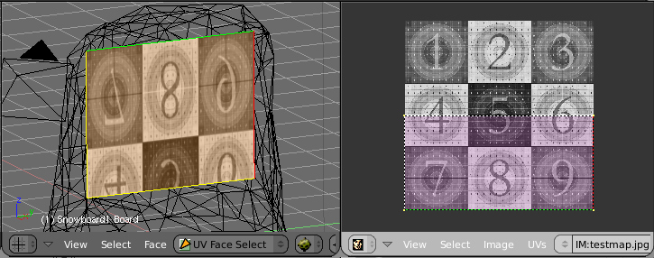
You need to UV-map the mesh that will show the user image to the lower half of texture space upside-down. Do not overshoot.
Here is a screen shot from Blender to show you how it's done (look at the coloured lines to get the orientation):

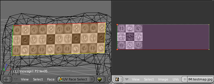
One full height of texture space is filled with the scrolling text, as billboards, upside-down. To prevent distortion you need to overshoot the mapping to the right, so it's width to height ration matches the mesh you apply it to.
Here is a screen shot from Blender to show you how it's done:

Basically set everything up like for a normal scenery object.
For billboards, select Billboard Texture as Texture Flags in the Mesh Settings window of the billboard mesh. You do not need to select a Texture or Texture Style for it.
For scrolling signs, select Scrolling Sign as Texture Flags in the Mesh Settings window of the scrolling text mesh. In this case you need to select a Texture. It is shown in the preview when the user selects the sign in the menu. You can change the Texture Style, but other ones as the default SIOpaqueUnlit are untested.
The best option is to load a billboard or scrolling sign SID from jonwil's collection on his page. You only need to set Extra Parameters to Sign for scrolling signs then.
The basic setup for billboards is to set Flag 26 and to keep Extra Parameters at None. You don't need to set Flag 26 for generic stalls with billboards.
The basic setup for scrolling signs is not fully tested, but at least you have to set Extra Parameters to Sign. If that doesn't work, try to set Scenery Type to Sign and Size Flag to Path Center or Path Edge (Join).
This section is so far unwritten and needs your help. If you want to write it, please apply here or here.
We all want nice looking 3D models for RCT3 but we must remember that a lot of folks out there cannot use high detail models without lowering the performance of the game itself. It is now possible to use Level Of Detail (LOD) setting when importing your custom scenery into RCT3, a feature that will have thousands of RCT3 fans out there grateful for your hard work.
First I'd like to explain a little about what LODs actually do and how to plan your model. LODs are simply a way of using multiple models for both different graphics settings and Draw Distances (DD). My computer's graphics card can handle some pretty complex 3D models, but other players' computers may not, so different LODs become very helpful for making happy graphics cards.
LODs also have assignable Draw Distances. You can set how far away a particular version of your scenery is displayed. If I'm over at one side of the park and I have a high detail model on the other, there really is no need for the computer to try to draw the whole thing off in the distance, or draw it at all if it's a tiny object that really doesn't need to be seen that far away. Remember that RCT3 doesn't really know what your object is and it certainly can't decide to just drop certain faces in an attempt to reduce the detail levels (there are some rules it follows, but RCT3 still needs information to optimally work). You have to do that yourself- but don't worry! It's really easy!
First lets think about the scenery item itself. For this tutorial, I'm going to use a sign with only two levels of detail. You can have more if you like, and I think three or four is probably more than enough for more complex items. If you were making a simple wall, there probably should only be just one level of Detail, but if that wall had a window, you might want to make several detail levels if, say, you had a fancy window frame. Lets look at the first, High Detail model:

My sign is essentially a wall, with some extra pieces in the way of a frame and some decorations. Here I've made all the detail levels needed in one 3D file- I simply choose to import the meshes designed for the intended detail level. Note that I've named the meshes in my 3D file according to the detail level they represent: HD= High Detail level, LD= Low Detail level, and AD= Al Detail levels. For the High Detail version, I've chosen not to import the Low Detail Meshes and added HD to the end of the model name at the very top. Let's now look at the low detail version:

Here you'll notice that I've simply chosen to not import the High Detail meshes and only import the Low Detail ones. What you don't see in either of the two images above are the actual mesh settings- In my High Detail meshes I've used a Gloss Reflection for the lamps, something that isn't needed for the low detail version for two reasons: 1- the low detail version is either going to be seen from far away or 2- the player's computer isn't very powerful and will be displaying the Low detail version, so why bog the computer down further if you don't have to.
Note
I've also included a DS in the Mesh Names that I intend to use a double sided texture setting- very helpful for my worn out little brain.
You will also notice that the name for this model in the top of the form has LD added to the end, to help identify it as a Low Detail model in the main Create OVL window. Again, remember that there is only one 3D model, I'm only changing what meshes to import for different detail levels. The model name at the top is used only by the importer and can be anything you want.
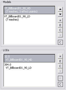
Lets now look at the two Detail Levels now set up and give them their Draw Distances:

The Models list (top) shows the two unique Detail Levels of the model I'm using. Note that this piece of scenery has some Effect Points and I've only set them up on the High Detail version. This is because Effect Points affect the entire Scenery OVL, not the individual Detail Level versions. If you add a light Effect Point to the high detail version, it will appear for all other versions of this piece.
The bottom window is where you assign the Draw Distances for each Level Of Detail version you have made. The numerical values are in the same Modeler Units that you may already be familiar with: a value of 4 would be the same as one RCT3 grid Square. So, in my examples here my High Detail version will be visible from 8 RCT3 grid squares away and the Low Detail version will be visible from 96 RCT3 grid squares away.
What does that actually mean? Remember that you are making versions of your scenery piece at different Detail Levels to be shown based on what the player's Detail Level Settings (in their graphics settings menu) are set at. So what's going on with this Draw Distance setting?
Well, each Detail level will be visible up to that distance away from the player's current position in the game: If their Detail levels are set low, then the Low version will draw from anywhere between 0 and (in my example) 96 RCT3 grid squares away.
If the player has higher Detail Levels set, then the High detail model will be visible anywhere from 0 to 8 RCT3 grid squares away, and then the Low Detail version will then replace it from that point up to 96 RCT3 grid squares away.
The Draw Distance value entered, while it does affect how far away the model will be visible, it also decides where the detail level is on the Detail Level Slider in the Graphics Settings LOD menu. I just made a piece with 5 levels of detail, set at (High) 32, (Medium) 64, (Low) 128, Extra-Low) 192, and (Ultra-Low) 384. These values caused the detail levels to change only at one extreme end of the scale: in order to view the lower detail levels I had to slide the control all the way over to the left, until it wans nearly off.
The values entered here might just be a subtraction from a fixed value- if you labeled the scale 4000 on the Left to 0 on the Right (values found in the Importer) then my model changes at intervals equal to these Draw Distance Values entered above on that scale.
The last thing I want to point out is where the player's actual Point Of View originates from: If you start the Attract Sequence Editor (Ctrl-Shift-0) and place a camera (insert) and then back away, you will notice that the camera is about 1.5 RCT3 grid squares behind where you think you actually were. This offset needs to be considered into your Draw Distance settings: I always add a value of 8 to my intended Draw Distance, which adds 2 RCT3 grid squares to the viewing distance. Just something to remember.
Finally, in closing. So what distances should you use? Well, that depends on the size and type of the object. RCT3 will impose different Draw Distances based on what the player has set in their Graphics Settings, not just the Detail Levels. There are different Detail and Draw Distance settings for different types of scenery, too: A tree can have a whole different set of levels than the path items, which in turn could have different levels than rides, supports, shops, etcetera.
Think about your object, how big or important it is when viewed from various distances, and then consider that the player's screen is only truly 2D in nature, and at some point any extra features that make your object 3D just cannot be drawn because there are only so many pixels the computer can actually use. A good example to look for are the heads of the peeps: at some point you will be too far away for the peep's ears to be drawn. If you were making a peep model, then you would make a detail level that does have some kind of simple ears (remember that Low Detail Levels are used on some computers when up close), but how complicated do they need to actually be?
This section is so far unwritten and needs your help. If you want to write it, please apply here or here.
This section is so far unwritten and needs your help. If you want to write it, please apply here or here.
In this section you'll learn how to create animated textures. Before we start, please remember that animated textures are a completely different concept than animatronics (3D animated scenery, “true” animation). It is currently not possible to create the latter with the importer. Ride events are a special form of animatronics, therefore animated textures cannot be triggered/used by ride events.
To create an animated texture you need to use the advanced texture edit window. Start by adding a texture to your object as normal but in the appearing file selection window do not select a file and press the button.
Note
You can also select a file, press and switch to the advanced texture edit window by pressing the button. Using this method you can also convert an existing static texture into an animated one.
For this tutorial though I'll assume that you created a new texture and pressed the button as described above.
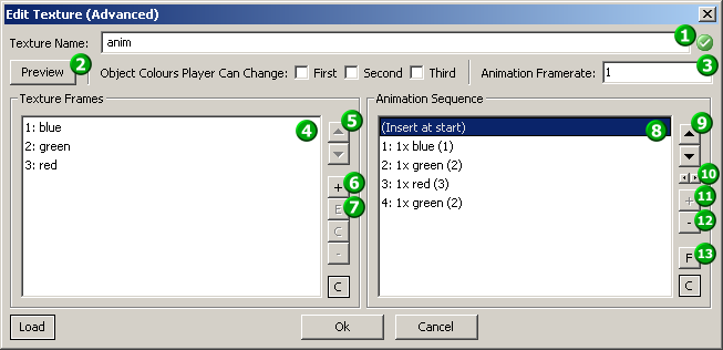
If you did everything correctly, you'll get the advanced texture edit window. The following screen shot shows you how it will look after creating a simple animated texture:

As of now, both lists and the Texture Name
 should be empty (Of course except for the
“(Insert at start)” helper item).
Before we continue, give your texture a name by entering into
Texture Name  .
.
Texture animation is like a movie that plays on your object. Texture frames are the unique still frames this movie consists of. Unique means that if a certain frame should occur multiple times in your final animated texture, you need to add it only once. Repetitions are created in the animation sequence (see Section 12.2, “Animation sequence”).
Now it's time to get to work and add some Texture
Frames. Press the respective button
 and select the first frame for your animation.
You'll get the Edit Texture Frame window, which
looks and works like a simpler form of the basic texture edit window.
You can also select multiple files instead of just one. This will skip
the Edit Texture Frame window and add the frames
directly to the list
  . The list shows the index of a texture frame and
the file name (without directory or extension).
You will note that as soon as you add your second frame, the names will be shown in red. Red means that the respective frame is not used in the animation sequence, which at this point is normal as we haven't created the sequence yet.
If you want to edit a texture frame, press the
button  or double-click on the frame in the list
 .
.
You can also change the order of the texture frames by moving them
with the up/down arrows  .
.
Important
Normally this will not influence your animation, that is only governed by the animation sequence! If you need to (e.g.) flip two frames in the animation, you need to freeze the animation sequence (see Section 12.3.2, “Freezing the animation sequence”).
As stated above, the animation sequence defines the order of play
of the texture frames. The Animation Sequence list
 shows the order top to bottom. Each entry in
order shows the animation sequence index, how often the frame is
repeated, the texture frame name and the texture frame index. Note that
you cannot individually change the duration of a frame, you can only do
that relatively by repeating it. Also keep in mind that texture
animation is cyclic, so after the last entry in the animation sequence
it restarts from the first.
To add texture frames to the animation sequence, select them in
the Texture Frames list  and press the Animation
Sequence button
  . You can then reorder the sequence with the
up/down arrows
  and change the repetition count with the
left/right arrows
  . Note that if you add a texture frame directly
before or after the same texture frame in the animation sequence, it
will also be summed up into the repetition count. The delete button
()
  deletes the complete entry in the list.
The last thing you have to do is to choose the speed of animation.
The Animation Framerate  lets you set the speed roughly in frames (or
rather animation sequence entries / repetition instances) per
second.
Now your animated texture is ready to use. Assignment to a model works exactly like for static textures, there is nothing you have to do differently in any other part of the import process.
This section explains a few things that are not absolutely necessary to know to create animated textures, but might come in handy, so I recommend to at least have a brief look.
The preview helps you to prevent confusion on animated textures
with lots of frames and/or complicated animation sequences. To show
(or hide) the preview, press the button
 . It does not provide you with a preview of the
running animation, but shows you the texture frame you selected last
in the Texture Frames list
  or the texture frame referenced by the
last-clicked entry in the Animation Sequence list
 .
.
To understand this concept, you have to realize how the
animation sequence is stored internally. Normally the editor gives you
the impression that the sequence is stored by name (changing the order
of texture frames doesn't influence the animation; if you delete a
texture frame, all animation sequence entries that reference it are
deleted as well). Internally the animation sequence is stored as
texture frame indices (the number in parentheses at the end of each
entry). If you change the texture frame order you'll note that these
numbers change, indicating that the internal representation of the
animation sequence changes (keeping the final animation constant).
Freezing by pressing the button
 will keep the internal representation
constant.
Before you tune out, I'll give you an example :-)
The example animated texture in the screen shot gives a flip-flop animation from blue over green to red, then back over green to blue. Not let's assume that I want to exchange blue and green in the animation (green-blue-red-blue-green-...). To do that I would switch the position of blue and green at the start of the animation sequence, remove the green frame at the end and add a blue frame.
Using freezing this can be accomplished quicker. First I freeze the animation sequence, then I switch the order of blue and green in the texture frames list and finally unfreeze the animation sequence - same result. It might not sound a lot quicker in this case, but this is a very simple animation, it can get much quicker in more complicated cases.
All of this may still sound a bit complicated, so go on an experiment a bit with it, I'm sure you'll get the knack of it soon.
A few things to keep in mind about freezing:
As long as the animation sequence is frozen, you cannot edit it.
If you remove a texture frame while the animation sequence is frozen, entries that reference it will be kept and some entries will now indicate that the frame they reference is gone. If you add a new texture frame, these references will become valid again (remember, reference is by index). If you unfreeze the sequence while it still has invalid entries, they will be removed.
This section is so far unwritten and needs your help. If you want to write it, please apply here or here.
Some information can be found on Belgabor's facts & figures page.
Atari® and Roller Coaster Tycoon 3® are trademarks of Atari Inc. All Rights Reserved.
The docbook css used for the html version of this document is based upon the one created by Chris Karakas.
This CSS stylesheet uses QBullets in links. Thanks to Matterform Media for providing QBullets for free. If you plan to use them on your website, please observe the QBullets usage terms.
